Design Process
Take a look at how this product was manufactured
There are four basic parts that we needed to develop.
These are as follows:
Lets start with the Base Plate
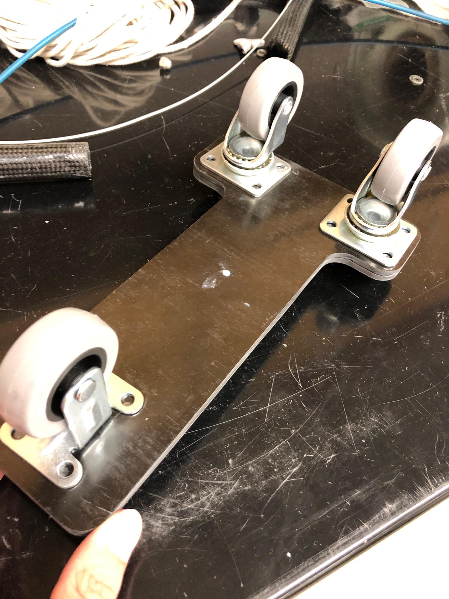
The base plate was relatively easy to make and used carbon pre preg. We used a [0/90]s type design with 8 of the 0 degree plys and 8 of the 90 degree plys. These were layered into a plate fixture and then placed into a press mold overnight.
The shaft is composed of an inner shaft and outer shaft.In order to create a shaft we had to use a mandrel on the filament winder.Rope was wound around the mandrel in order to acquire the necessary thickness.A layer of vacuum bag was placed over the rope covered mandrel for easy removal.Resin was then acquired to begin the coating process. A program was created for the filament winder to apply the carbon fiber on the mandrel.The resin was applied to the carbon fiber as it was wound around the mandrel.Once complete, the mandrel was allowed to cure for 24 hours
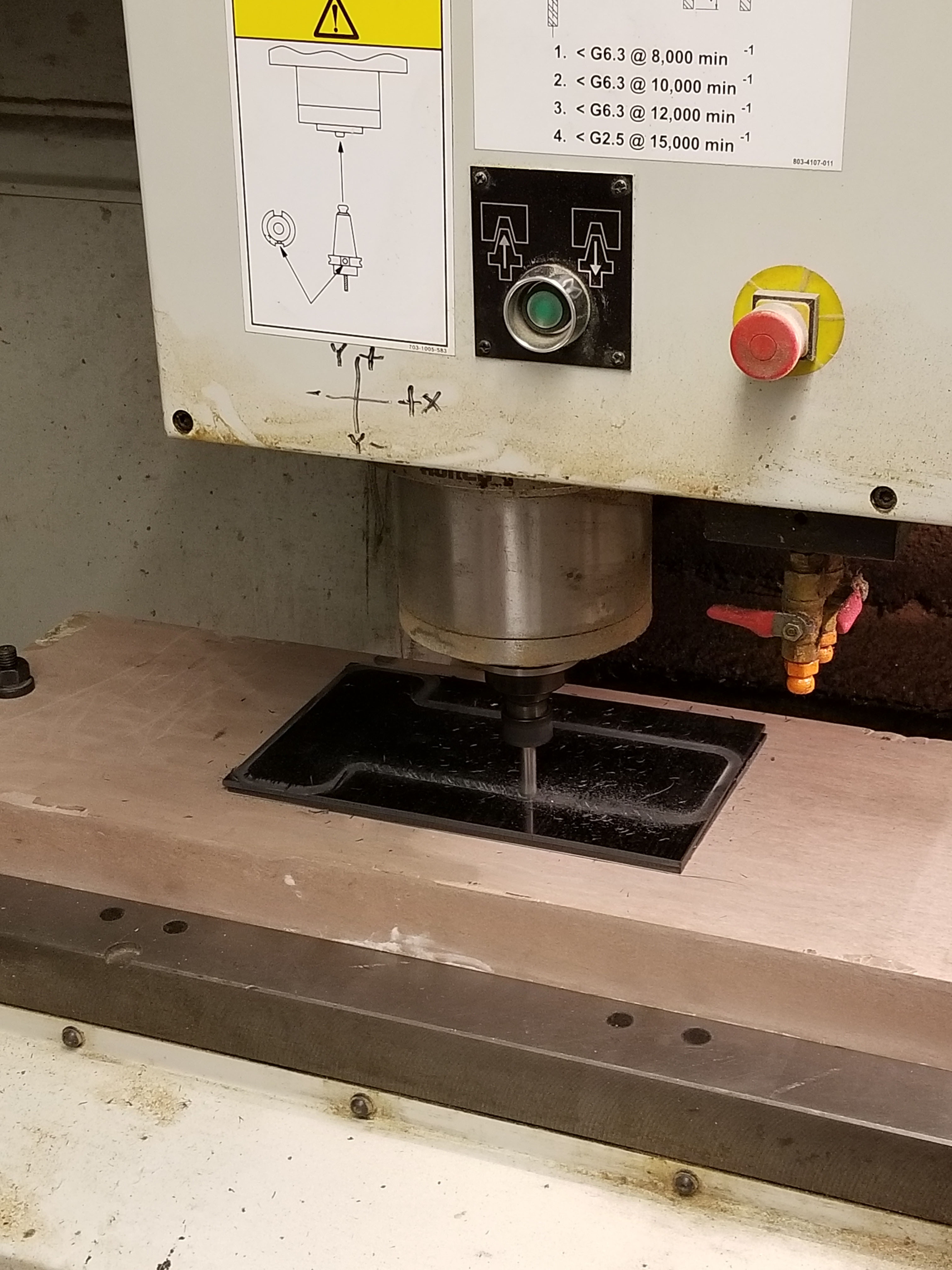
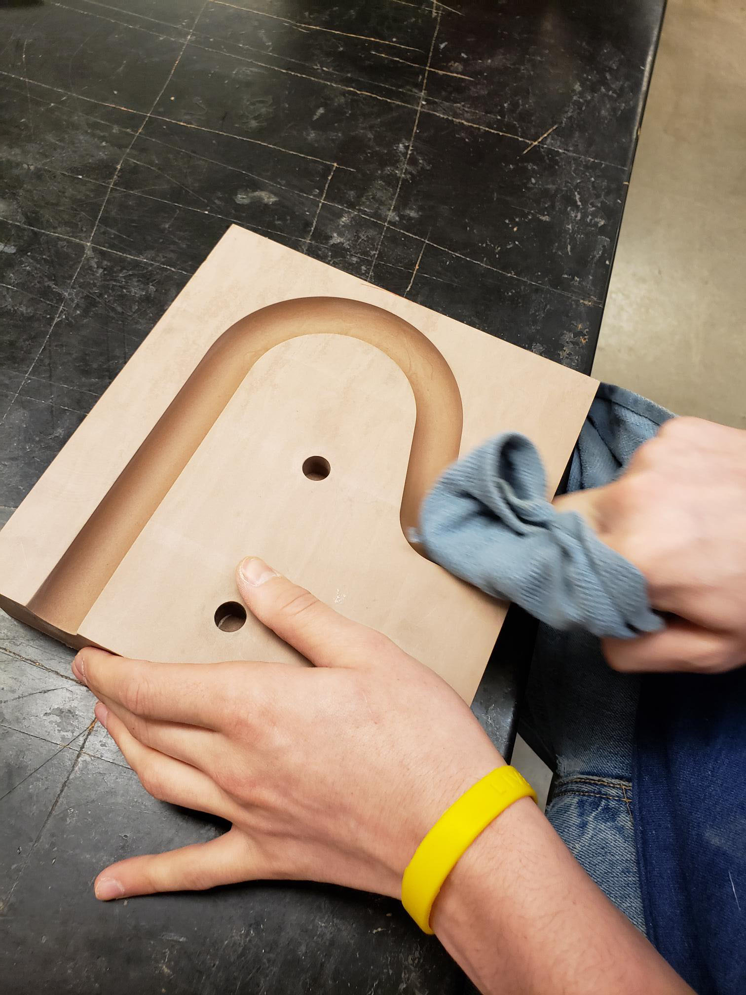
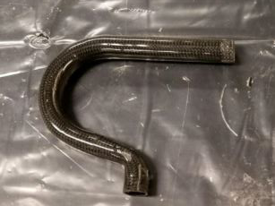
The handle was the most difficult part of this project.The first thing that needed to be done was to cut out a mold from a structural foam block. In order to do this, Autodesk Fusion 360 was used to generate a toolpath which was then exported as a g code file. The g code file was uploaded via usb into the CNC mill. The resulting toolpath was cut over a period of 3 hours. Once the CNC mill was finished doing its job, the two part mold was ready to be used to make the part. A bike tire inner tube was used as an inflatable bladder. A carbon sleeve was placed over the inner tube and then set into the two part mold. Then it was inflated and allowed to cure for 24 hours
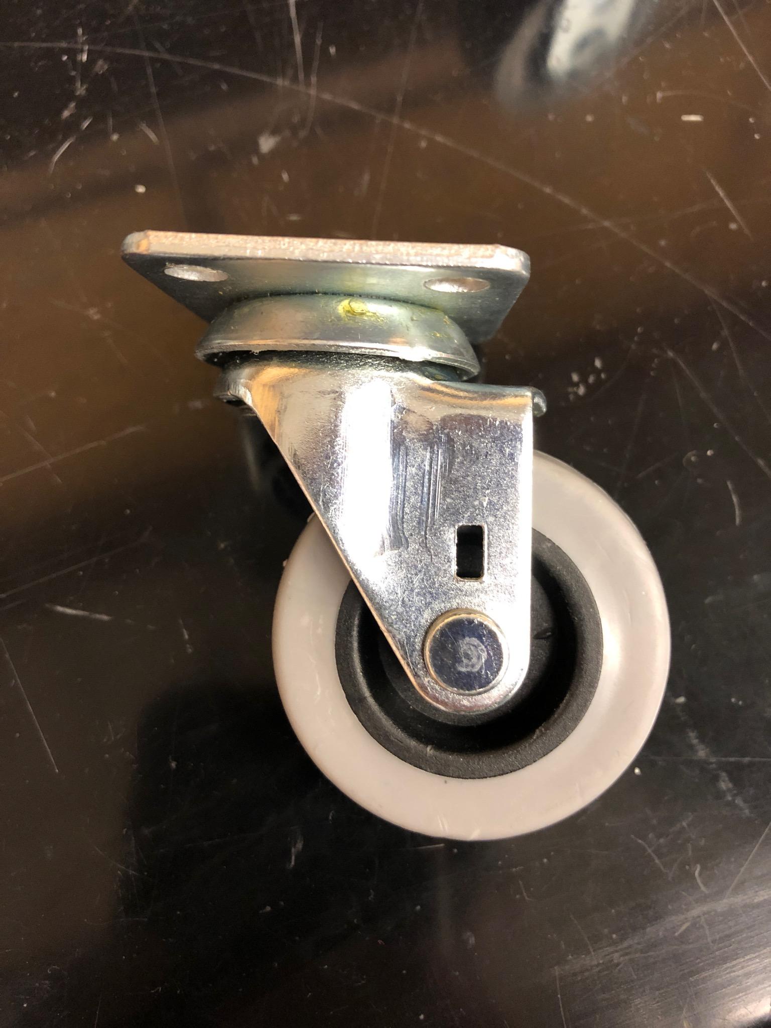
The wheels were purchased from a website.
